I knew from the moment I became aware of a 3D Printer that you could have in your house I wanted one! I didn't know how, or where, or even if I would be able to get the money but I knew I had to have one for sure! It was early on that I became fascinated with the whole Delta design. I loved the way they moved, their speed, pretty much the way they move the effector plate around in 3D space while still holding it level and being so very precise!
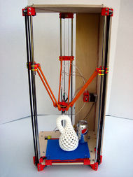
The Rostock 3D printer was originally developed by Johann C. Rocholl from Seattle, USA, his first Rostock was built in 2012. Instead of your standard xyz gantry system, the Rostock uses 3 arms that are attached to 3 vertical axes, each independently driven by stepper motors. Also taking advantage of an extruder that is not a direct drive, the filament is guided to the hot end by a bowden tube (PTFE tubing). The end result? High-speed positioning, fewer parts, lighter setup and a look that is guaranteed to turn heads.
Below is one of the first videos of a Rostock in action that got me hooked!
Below is one of the first videos of a Rostock in action that got me hooked!

Ok, enough of the history lesson, lets get back to the subject at hand, my Rostock Max! So I was searching the internet one night as I often do when it popped in my head to, for curiosity sake, see how cheaply I could get my hands on a 3D Printer. First thing I found was the MakiBOX, which I got really excited about cause I could get one for $200 bucks! Oh wait that was a maybe get one for $200 with a 6 to 12 week lead time at least! Plus the more I searched the more I realized that while the cheaper 3D printers are great, because their cheap, but unfortunately with that small price tag also comes a very tiny build volume or printing area. I wanted to be able to print more than just trinkets! I wanted to design, invent and make my ideas a reality with no restrictions! It was about this time I realized I absolutely loved the Delta design printers and was doing research on what goes into building a Rostock, how much it would cost, ya know all the normal stuff. I thought I was going to need to build one from scratch to get what I wanted, which I had no doubt that I could do it, I just didn't know how long it would take or how much money would go into it and being worried about making mistakes that cost me a lot of time and money.
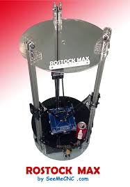
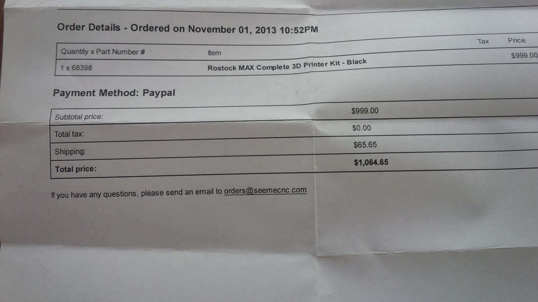
Then while perusing the price compare guide on a great site 3ders.org, I found it! It had everything I wanted, everything I was hoping for, it was a Delta design and had a big build envelope along with a proven track record! It was made by a company called SeeMeCNC, the name of this gift from above was the Rostock Max. It was a kit that you had to build yourself, which I think is half or most of the fun, it came with absolutely everything you need other than, some Kapton Tape and some Permatex Ultra Copper RTV High Temp Silicone. It also came with a pretty steep price tag at $999! Which isn't bad considering everything you get along with the quality, great customer service and a huge following on their forum (forum.seemecnc.com) for any technical info or help you may need. The guy who wrote the guide on how to build the thing is even on the forum quite often! All in all that was still a big price for me! So there it is, I was hooked, I searched on it every day, read so much about it both good and bad and even went ahead and read the build guide a few times for the fun of it cause I wanted one so bad. Long story short, my wife got tired of hearing me talk about it all the time and agreed if I could come up with $700 of it on my own from selling stuff on eBay then I could use some of the money we had in savings for the remainder. LOL, who knew it would only take me like a week and a few days to raise the money, before I knew it my dream had come true and I had ordered a Rostock Max from SeeMeCNC and it was on its way!
Then while perusing the price compare guide on a great site 3ders.org, I found it! It had everything I wanted, everything I was hoping for, it was a Delta design and had a big build envelope along with a proven track record! It was made by a company called SeeMeCNC, the name of this gift from above was the Rostock Max. It was a kit that you had to build yourself, which I think is half or most of the fun, it came with absolutely everything you need other than, some Kapton Tape and some Permatex Ultra Copper RTV High Temp Silicone. It also came with a pretty steep price tag at $999! Which isn't bad considering everything you get along with the quality, great customer service and a huge following on their forum (forum.seemecnc.com) for any technical info or help you may need. The guy who wrote the guide on how to build the thing is even on the forum quite often! All in all that was still a big price for me! So there it is, I was hooked, I searched on it every day, read so much about it both good and bad and even went ahead and read the build guide a few times for the fun of it cause I wanted one so bad. Long story short, my wife got tired of hearing me talk about it all the time and agreed if I could come up with $700 of it on my own from selling stuff on eBay then I could use some of the money we had in savings for the remainder. LOL, who knew it would only take me like a week and a few days to raise the money, before I knew it my dream had come true and I had ordered a Rostock Max from SeeMeCNC and it was on its way!
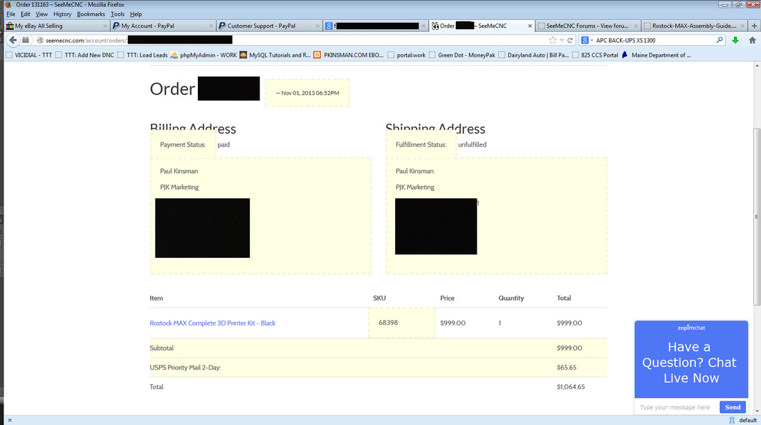
That's my order, as you can see I opted for the $65 2-Day Priority mail through USPS to get it faster but turns out even though they have a mail option they call 2-Day it is not guaranteed to be 2 days, it will be there within 5 days, it took 4 days to get to me, I would have been better off paying half the money on UPS ground, at least they get stuff there when they say they will! Anyhow, now that my rant is over, lol, we can continue.
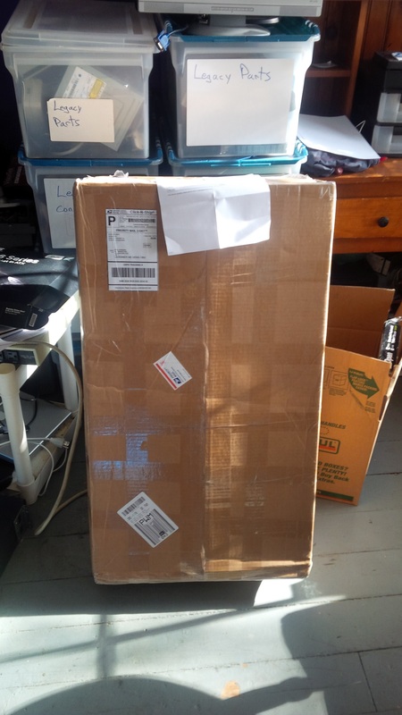
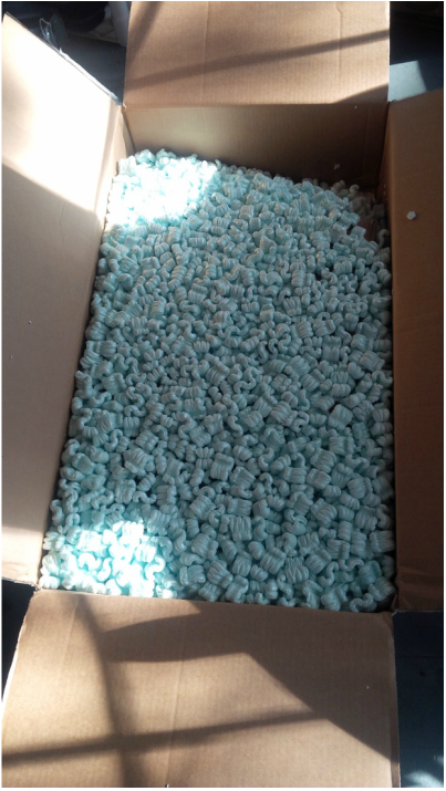
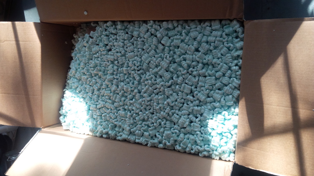
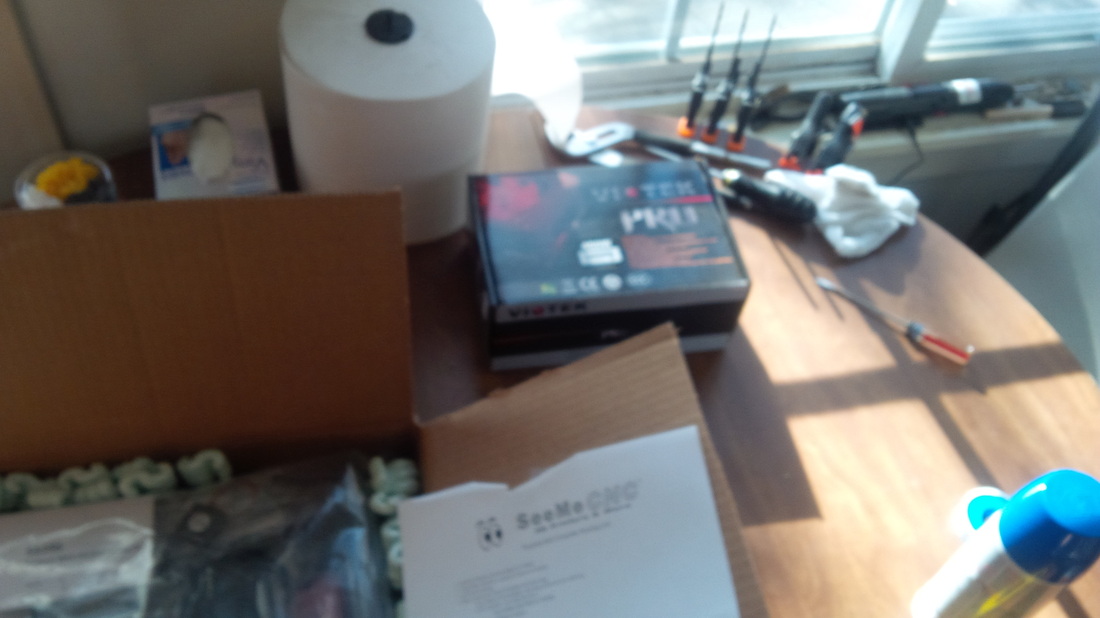
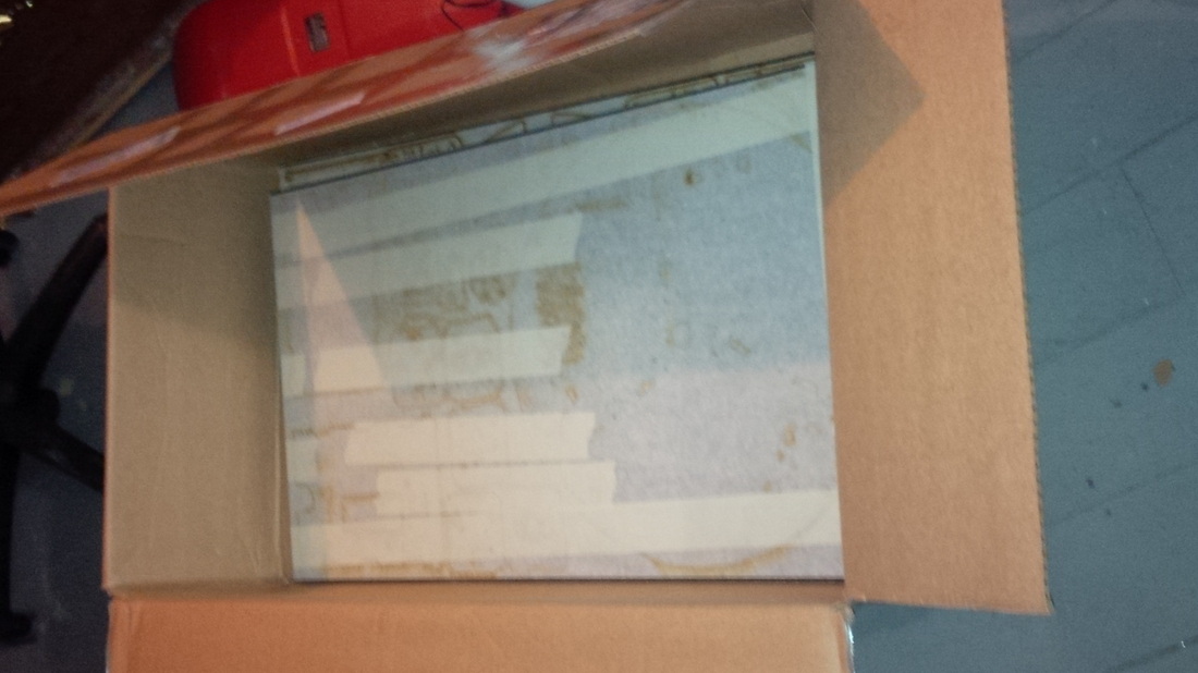
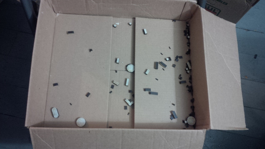
It's here!! Finally!! Wow look at the size of that box, it was a lot bigger than I expected, this is going to be one big machine! I carefully cut the tape along the seem and opened it to find a massive amount of packing peanuts, lol! Tons of em!
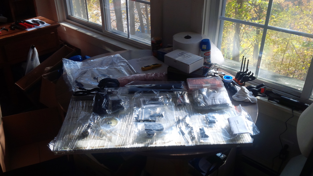
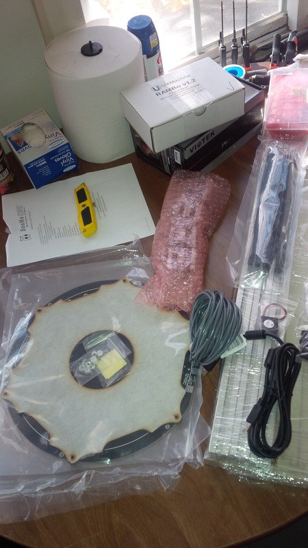
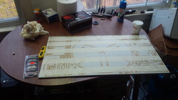
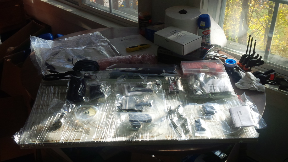
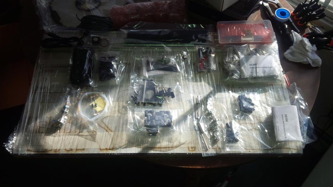
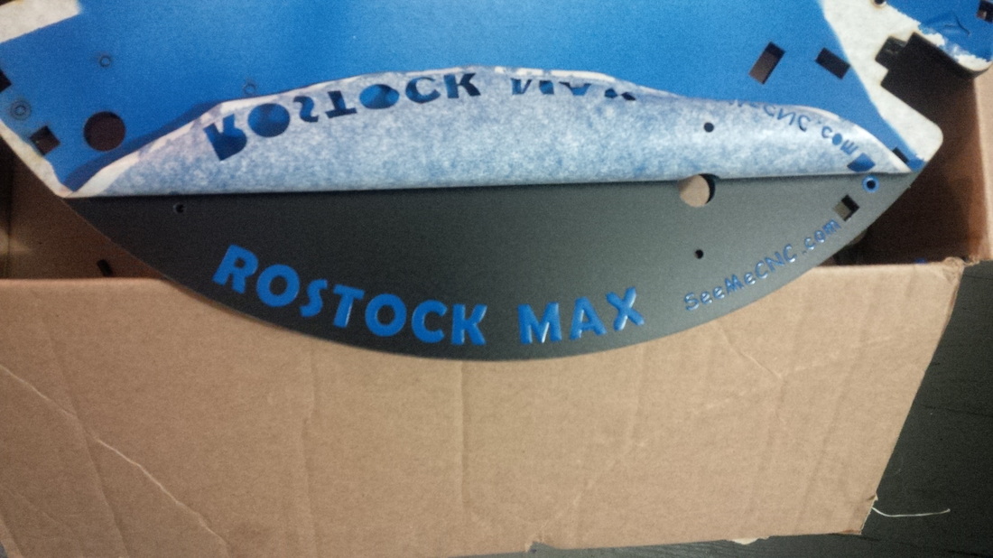
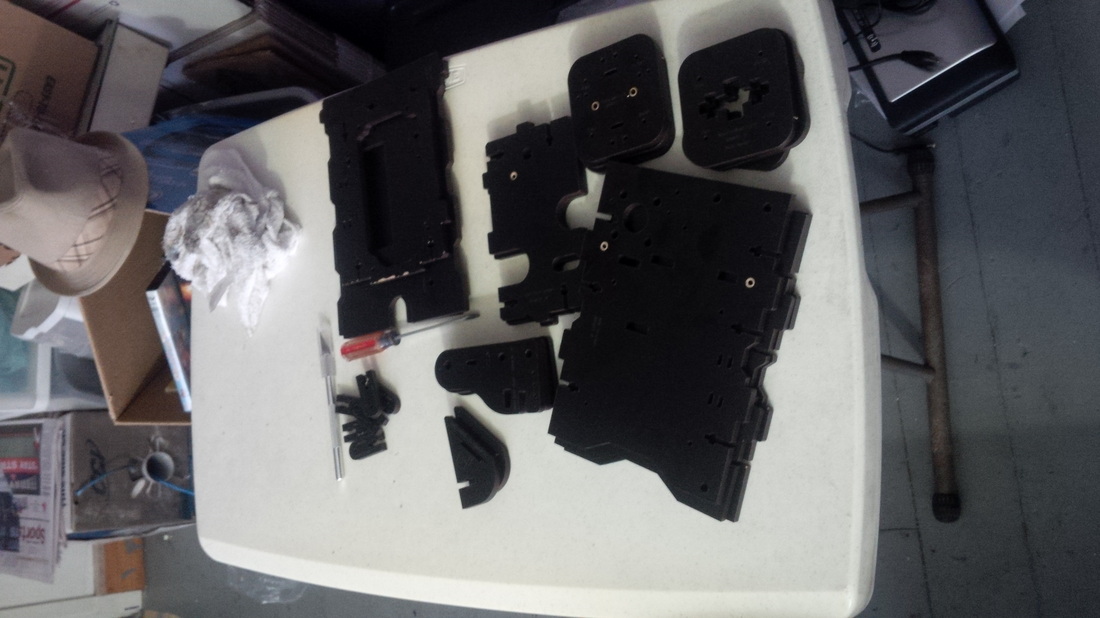
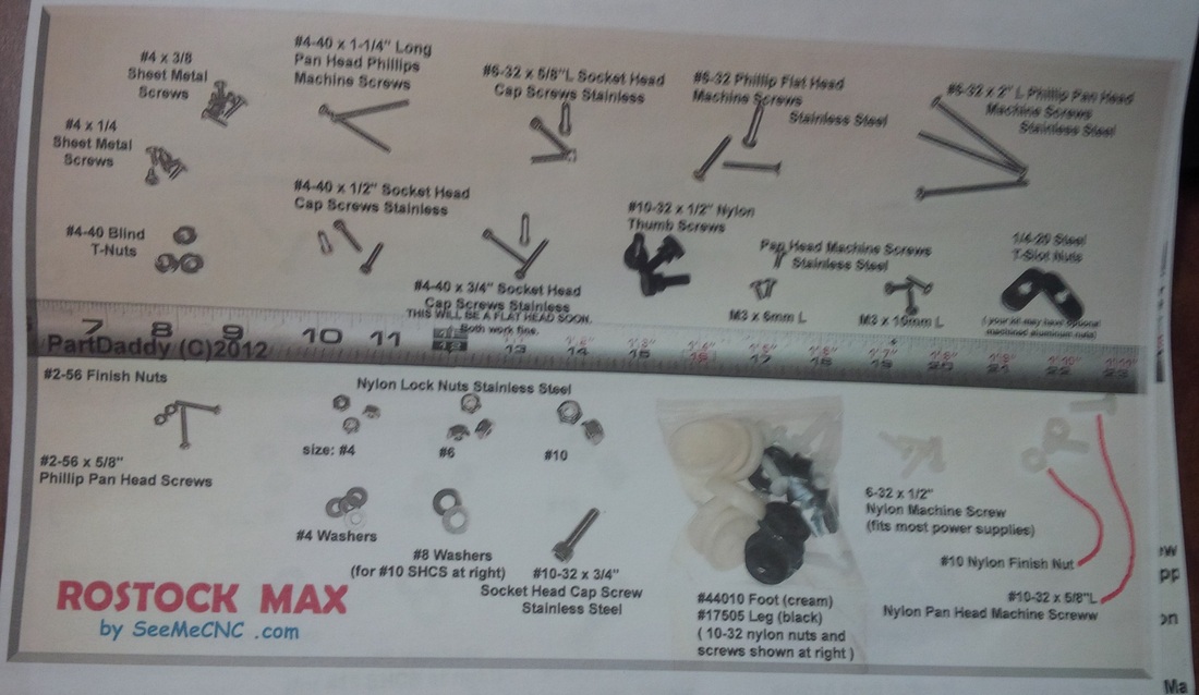
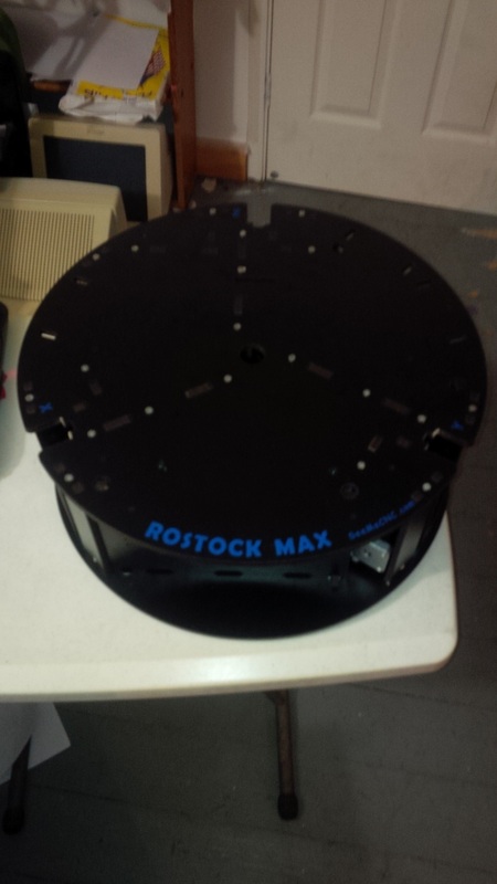
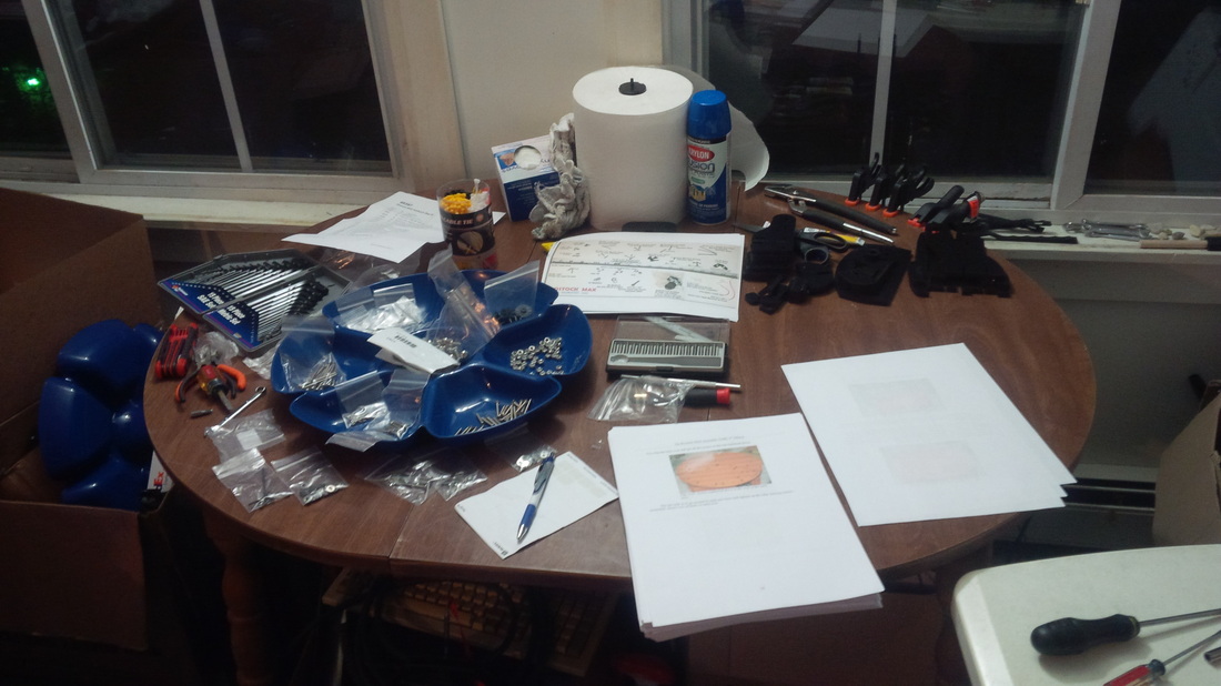
So first thing after my time pawing at everything with my ohhh's and ahh's was to set everything out and make sure I actually had everything that was supposed to come in my kit, so I set everything out on the table in my workspace and did just that.
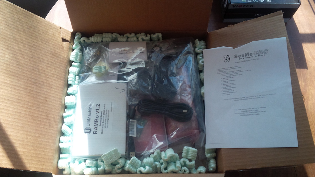
Look below, they even include the extra wire you need to complete the build, this kit comes with it all!
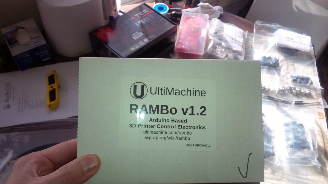
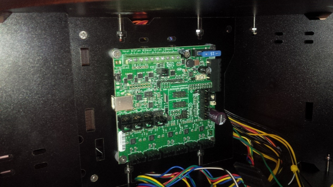
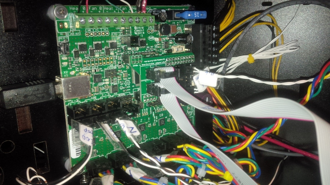
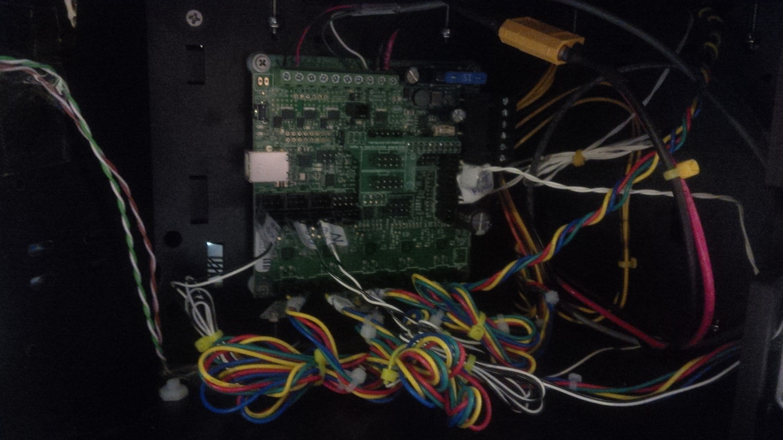
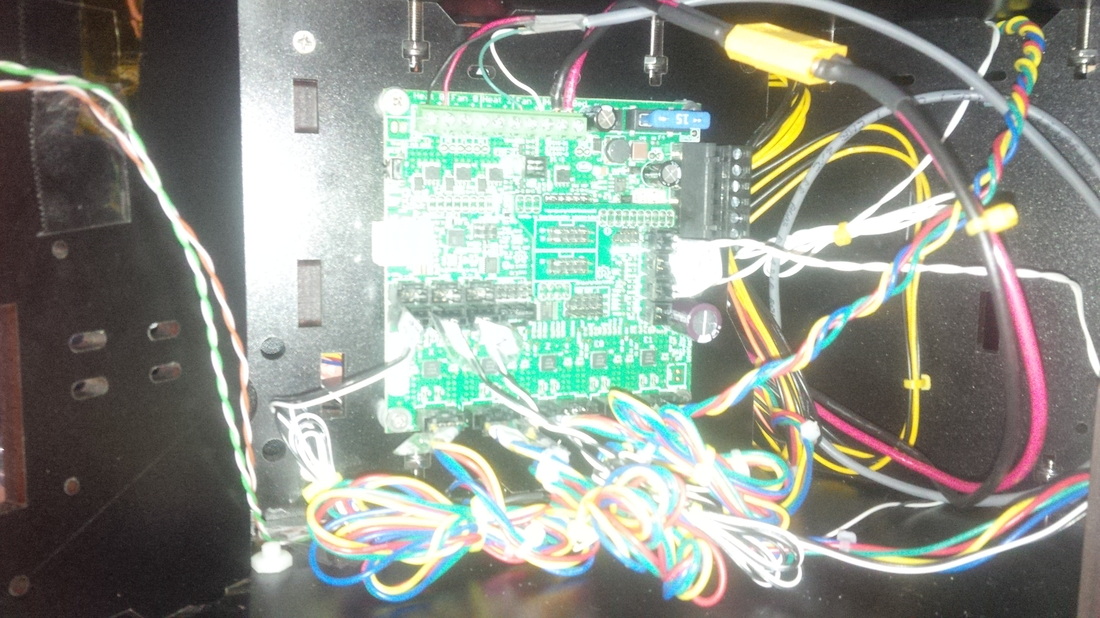
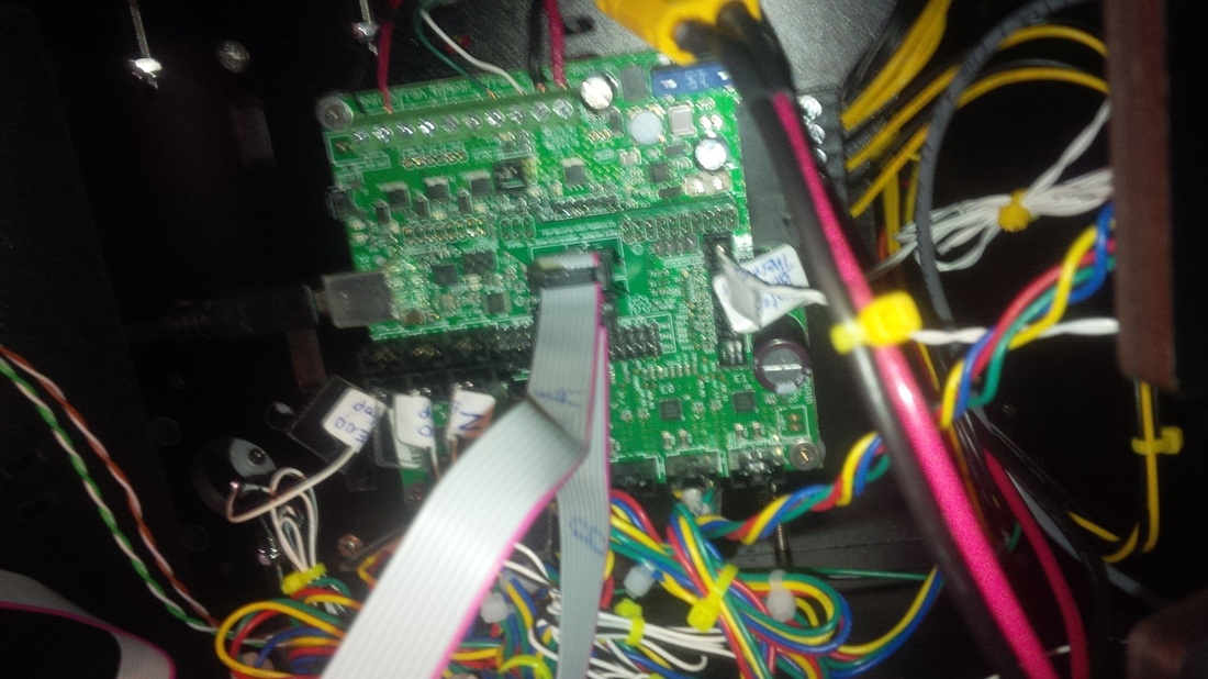
This kit comes with a RAMBo v1.2 control board from Ultimachine!
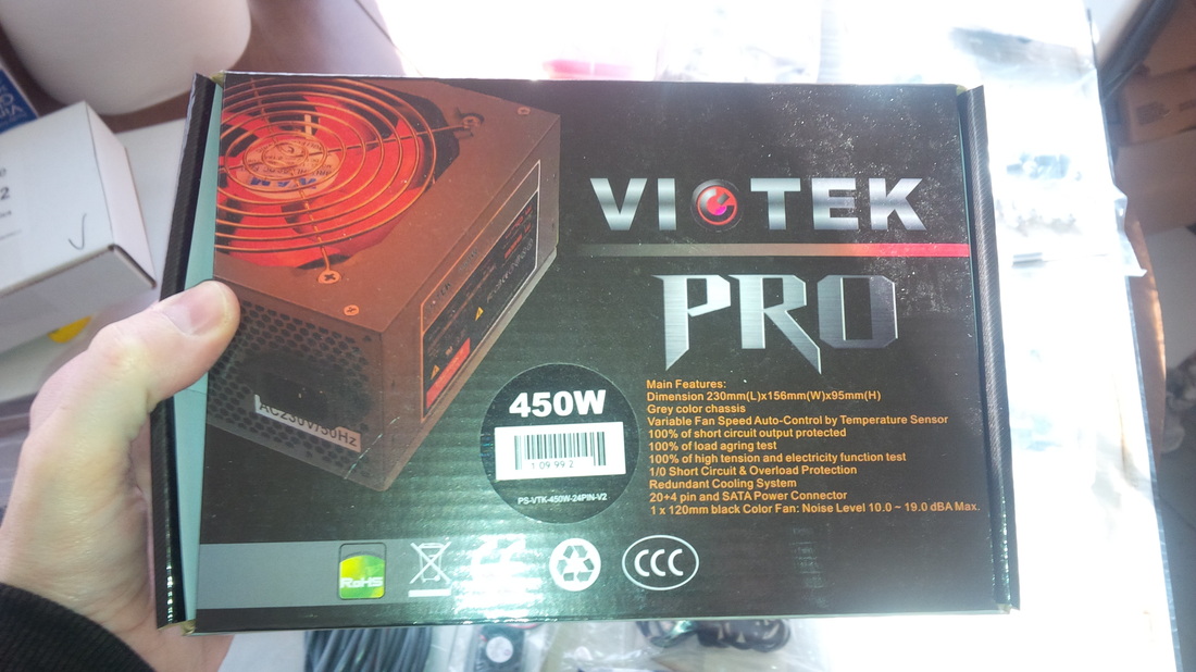
Also included is a 450 Watt Viotek Pro power supply unit. ( Now that I've been printing with this machine I think I want to upgrade to another power supply for the heated bed alone. It heats up fine with the Viotek but takes too long for me :-) )
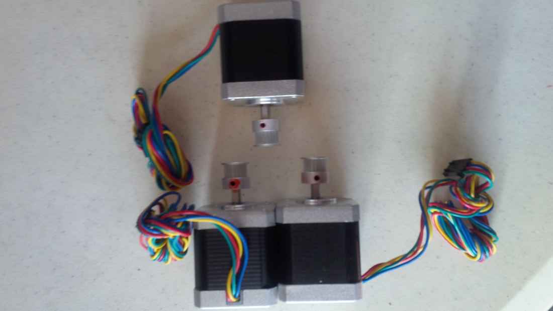
Then the NEMA 17 stepper motors, four of them, one for each tower and the extruder.
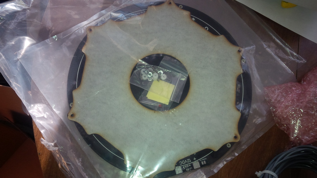
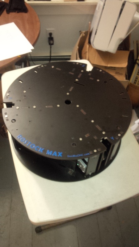
Did I mention that this thing has an 11 inch diameter circular build area by about 14 1/2 inches tall!! This was one of the reasons I went for this kit! Rostock Max + Onyx heat bed = huge build volume!!
Here's a video of me going through the packing list to make sure everything arrived alright, you don't have to watch it or anything I just thought I would include it with my build log here.
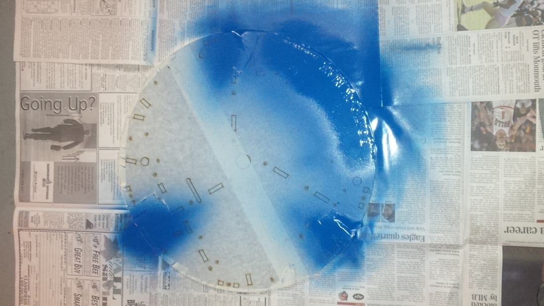
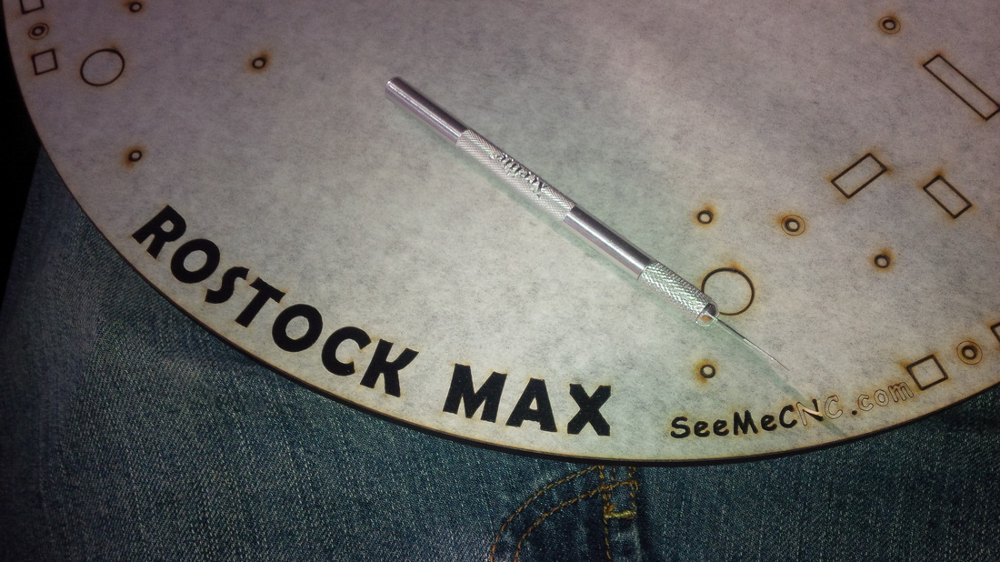
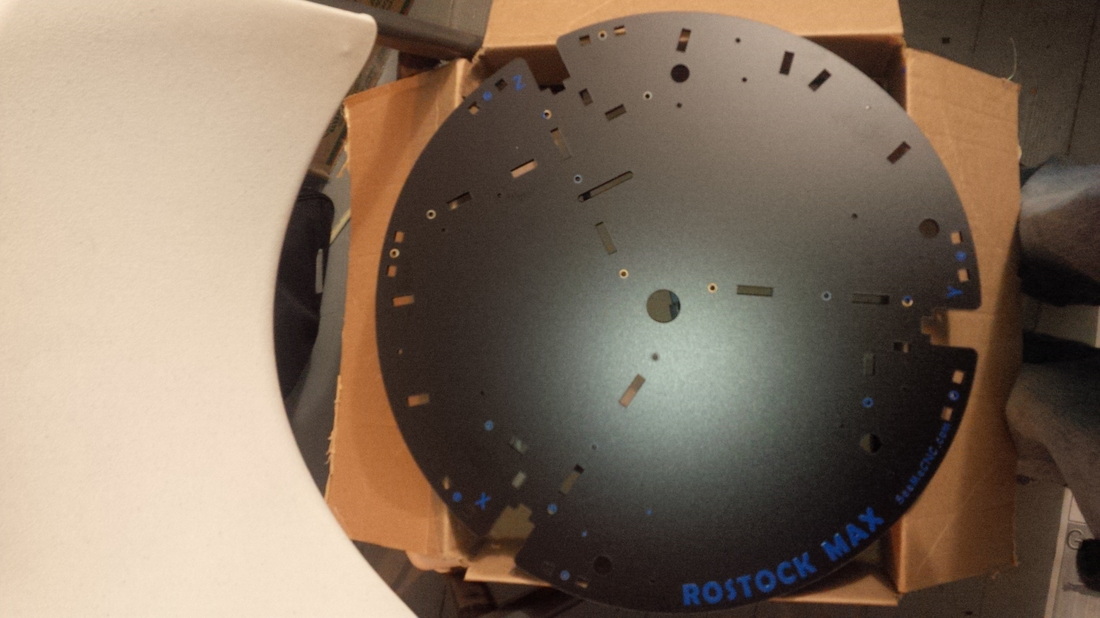
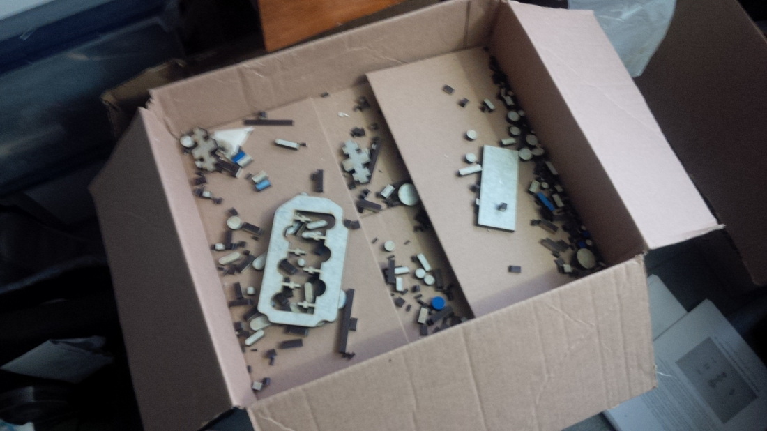
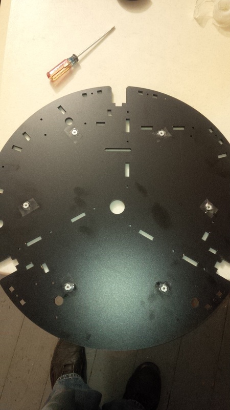
First things first, lets go the the SeeMeCNC Forum and download the latest version of the Build Guide , it's probably a good idea to go ahead and read through this once before you start building so nothing catches you by surprise! Next you have got to clean up the laser cut melamine pieces because they are covered in some masking tape. Top few strips are to hold everything in place during shipping and the first layer is to protect the melamine from the laser cutting it so you'll have nice clean edges. This can be kind of a pain but is more just time consuming rather than hard. For the masking around the lettering I just used my fingernails to scrape it off. Now hold on a minute, if you would like to personalize your Rostock Max by painting the edges or lettering make sure to take advantage of the fact everything is already masked out for you! If you want to paint the whole pieces I guess you can just rip all the making off. I decided to paint the lettering on the bases top a nice blue color and I will continue with this color scheme as I add things like sheaths for the wiring and such.


The little blue circles in the photo below are the spots that need to be countersunk, that's just masking tape I haven't taken off yet, all the holes to be countersunk have had the melamine cut in a circle around the hole to make it easier for someone like me who has to do it by hand as I have no drill bits to countersink heck I don't even have a drill! lol!


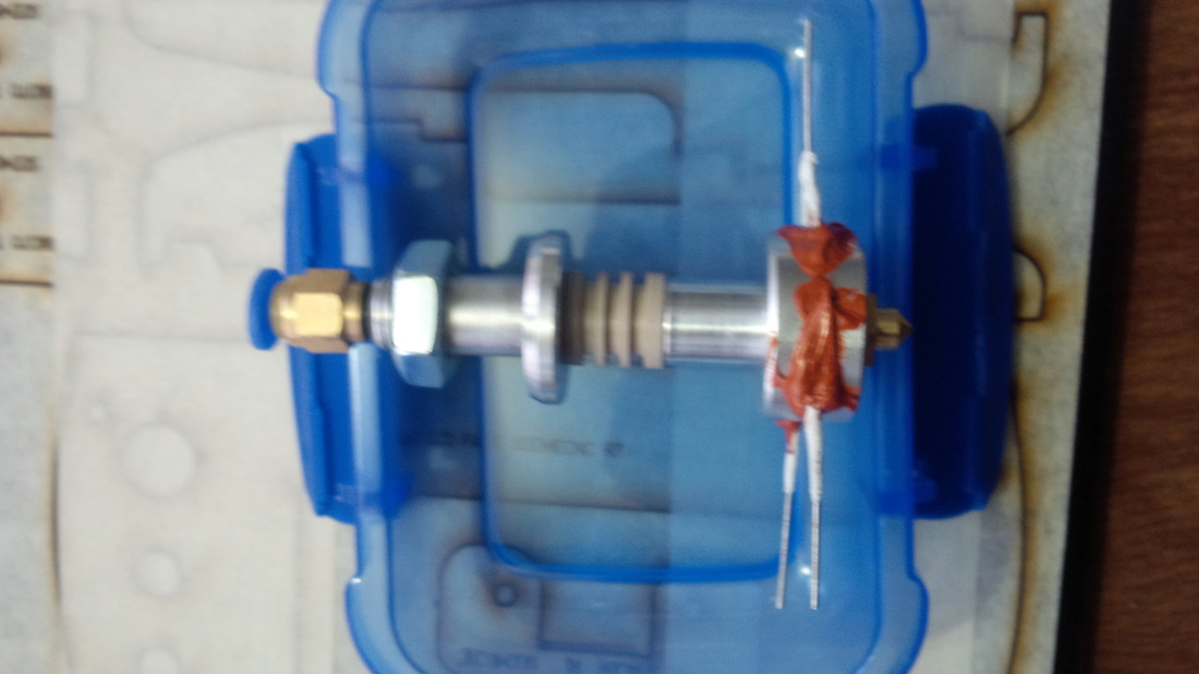
At this point I would suggest starting to get the Hot End together so the RTV High Temp Silicone has time to fully cure. Time till fully cured is 24 hours BTW. So the first thing you need to do is grab the Hot End components. The two big resistors go into the two larger through holes in the heating block, the Thermistor goes into the smaller hole. We need to insulate the leads of the resistors so they do not touch any metal on the Hot End or they will short out and then your Hot End will not work. It is recommended in the guide to use some PTFE tubing you can order online for this purpose however I wasn't able to order any of this as I had just spent a butt load of money on this kit! So, I improvised, I found some PTFE plumbers thread tape at the local hardware store for less than a buck for a little roll of it. Just cut maybe a couple inches length off the roll and then wrap the leads closet to the resistor. Once you have it all wrapped on there just go ahead and run the whole thing between your fingers applying a little pressure and it will form into a nice little tube, if one slides off by accident you can even just slide it back on like a tube. There is no reason this shouldn't be fine as it is still PTFE material and is still rated for the higher temperatures just like the tubing, mine has been running fine and this is what I used seen in the picture to the left. Once done with that, you'll notice that the resistors are a little too small to fit snugly into their holes so we need to use a strip of aluminum foil and wrap it around the resistor until it fits snugly into the hole. Make sure that your strips of foil are not too wide as you do not want them to touch the leads and short it out. Now that you have each resistor fit snugly into their respective holes we need to seal them in with some of the Ultra Copper High Temp RTV Silicone, you should be able to find this in most automotive parts stores if not you can get in on Amazon for less than $10. Once you have enough RTV in and around the holes so the resistors will be nice and secure you need to set this aside for at least 24 hours (no cheating or it will be your loss) until the RTV has fully cured.
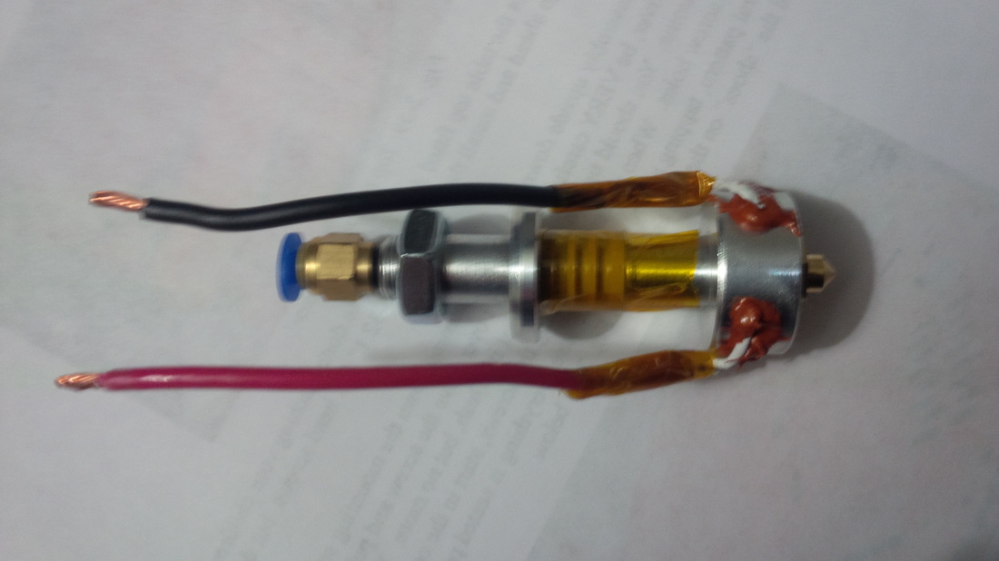
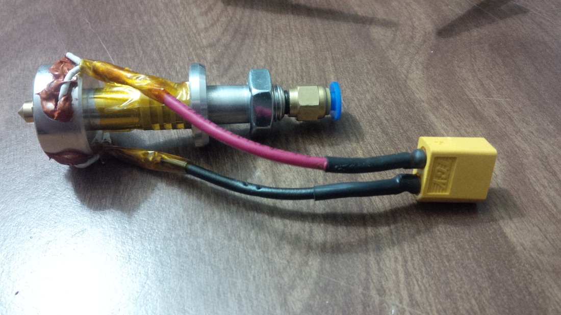
Now that the RTV has fully cured we need to twist the ends of each resistors leads together nice and tight. ( make sure you are twisting the leads from each resistor together and not twisting them with themselves - don't ask - just make sure they are correctly twisted and save yourself some trouble! ) Grab some needle nose pliers and make sure you have them twisted nice and tight then take your wire cutters and just nip the ends off so they are of an equal length. Now cut yourself 2 3" lengths of wire(I used 13 gauge), these will be your connection wires for the hot end resistors. Because the wires do tend to get quite hot we cant solder the wires to the resistors, the solder would just melt off and make an awful mess, so you need to use uninsulated connectors, don't worry cause I'm gonna wrap em up with some Kapton tape once the wires are crimped on to the resistors. At the end of the wires I soldered on an XT-60 connector so I can easily remove the hot end for any maintenance or whatever reason I want.
Now that that's done we are half way done with the hot end. Now you have to install the thermistor, this is a very delicate piece of equipment remember to be careful when dealing with your thermistor. Take some PTFE tubing and cut 2 inch long pieces and slide them over each one of the leads. Now cut 2 3" lengths of wire (I used 24 gauge). Before soldering the wires to the thermistor leads make sure you slide some shrink tubing over the wires so you can protect the joint. I put one on each lead then used one that was a little larger to wrap both into one for added protection. Once that's done add the connector of your choice to the end of the wires (I used Deans connectors I think). Once that is all set up take a little blob of RTV and coat the sides of the thermistor, leave the tip bare for better temperature readings, now put it in the hole on the opposite side of whats showing in the picture above and seal around the outside with some RTV silicone, let that sit for 24 hours at least before you do anything else with it. Now I was done with the hot end!
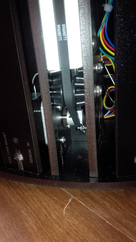
Now that the Hot End is all set up and the RTV is curing I had one last sheet of melamine to remove the masking tape from before I could start preparing for the actual build. Once I had all the pieces free from their masking tape I went ahead and countersunk all the spots that need that done. The holes that need countersinks are found by looking for the holes that have another circle lasered around them. You can do this as the build goes on or all at once in the beginning, its up to you. I chose to get it all out of the way before I started the build. I didn't have a countersink bit so I had to use a razor blade, you can see it in the picture to the left. This step was kind of a pain without a bit but I managed, if I ever build one again I will make sure to get a countersink bit! Once I had all the holes that needed it countersunk I was ready to begin the actual construction of the base! Oh wait, before I started the base I got the pulleys installed onto the X, Y, and Z stepper motors. On the forum at SeeMeCNC people talk about grinding a flat spot on the shaft of the steppers so the pulley has a flat surface for the screw to press against but low and behold when I got the stepper motors out they already had the flat spots on them (must be an upgrade in the kit). That saved me some work I wasn't looking forward to!

You want to make sure that the top of the pulley is in line with the top of the shaft before you go ahead and tighten down the screw, also you want to add some thread locker before you place the screw in the hole and tighten it down so it doesn't come lose from vibrations and such. Once I had this task done I could really start on the base of the Rostock Max!
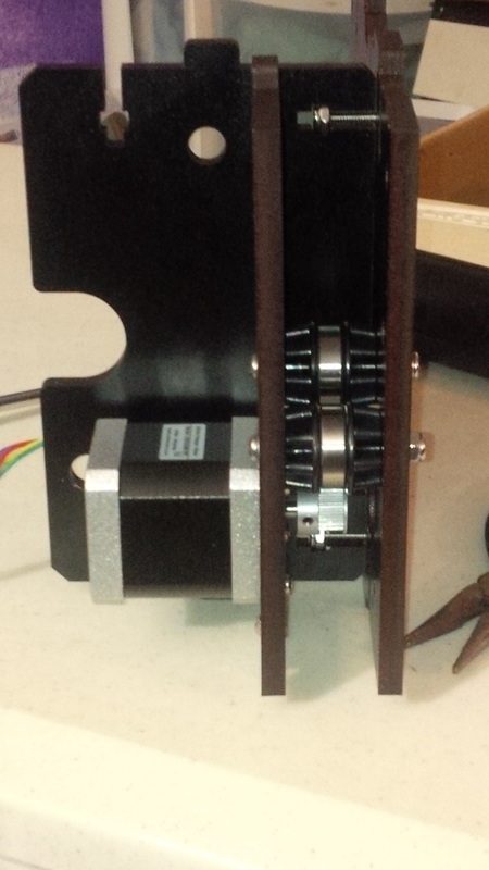
The base is made up of three sections, one for each tower and it holds the stepper motor and also the idler bearings for the belts. These sections were not hard to build, you just want to make sure you do not fully tighten all the screws down just yet as it will make it easier when installing the top and bottom of the base if there is a little wiggle room. Once I had all three of these sections done I could attach them to the base. However before I could attach them to the base I needed to install the feet on the bottom first.

Here are the 3 sections all assembled and attached to the bottom plate of the base along with the little support spacers. Notice that I have all of the wiring routed into what will be the "electronics bay" which is where the RAMBo board is going to go. Next up you will need to place the doors in their locations. So far it is all going together quite well, it is pretty straight forward.
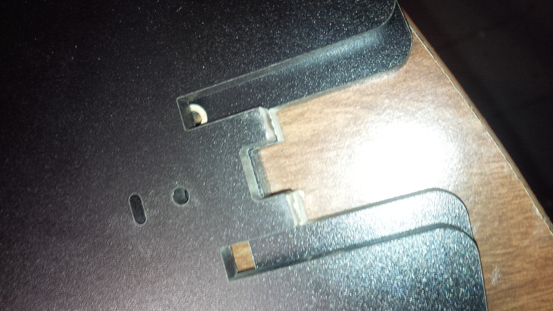
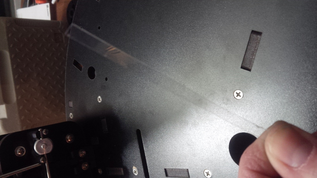
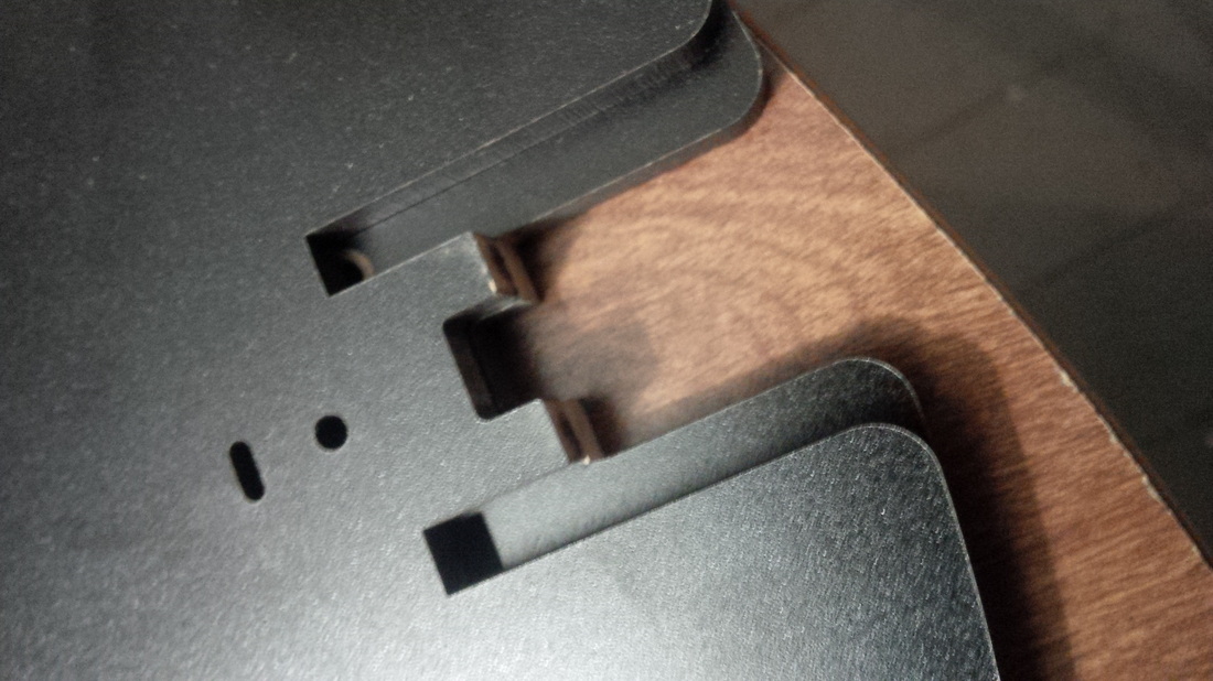
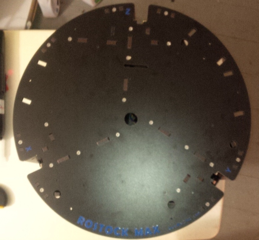
I almost forgot to mention that you should check to make sure the top of the base and the top plate of the machine all match up when you lay them on top of each other when building the Rostock Max. As you can see in the photo above I had to file the tabs down a little bit in order for all three locations to match up otherwise it would be darn near impossible to get the t-slot extrusions all squared to the bottom base as well as the top plate of the machine. If the towers are not square to the bottom and top then you will introduce errors in your prints that you will never be able to figure out!

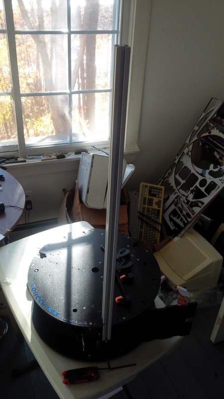
Once you have the top of the base fit into place you can start going around and tightening all the screws completely. I started with the bottom of the base and tightened in a spiral direction starting from the center working my way out. Then I tightened all the screws on the inside of the base and finally the top of the base in the same spiral pattern as the bottom. Now that everything was tight it was finally time to erect the three towers!

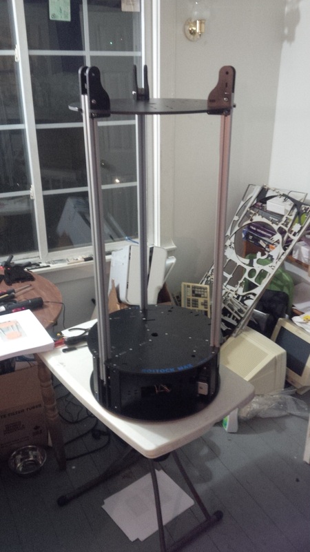
When your installing the t-slot extrusions into their specific channels there is a mark from the laser to tell you how far to put the t-slot in, right directly below that mark is a slot in the melamine meant for routing your wires, there are the same slots in the top pieces as well. All of these slots are at exactly the same location on all the pieces so what I did (and many people on the SeeMeCNC forum as well) was to use a little allen wrench that fit in perfectly as a stop so I would know how far to put the t-slot extrusions. Doing it this way ensures that the distance between the top of the base and the top plate of the machine are the exact same distance or all three towers. Once you have the t-slot in place loosely tighten the screws that hold it in place and grab a large framing square and square the tower with the top of the base, once it is square then you can tighten the screws all the way. Once you have the top all together and ready to slide on the extrusions I used the same method as the base to get the right distance. When the top is on the machine you have to flip it upside down and ensure the towers are square to the top plate as well, which it should be if you use the obstruction method for placement of the t-slot extrusions. If it isn't square then you have to make sure you have whatever you were using for the obstruction method in place and adjust the tower so that it is square to the top. Otherwise as I said before you will introduce errors into your prints that will drive you nuts!!

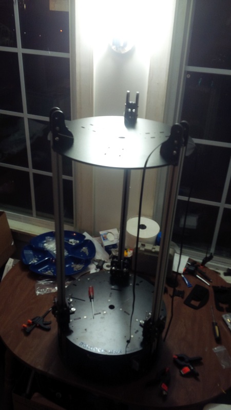
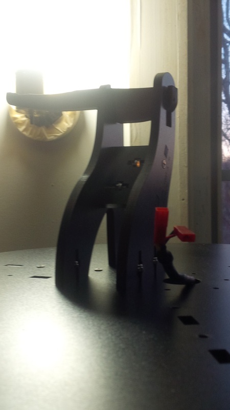
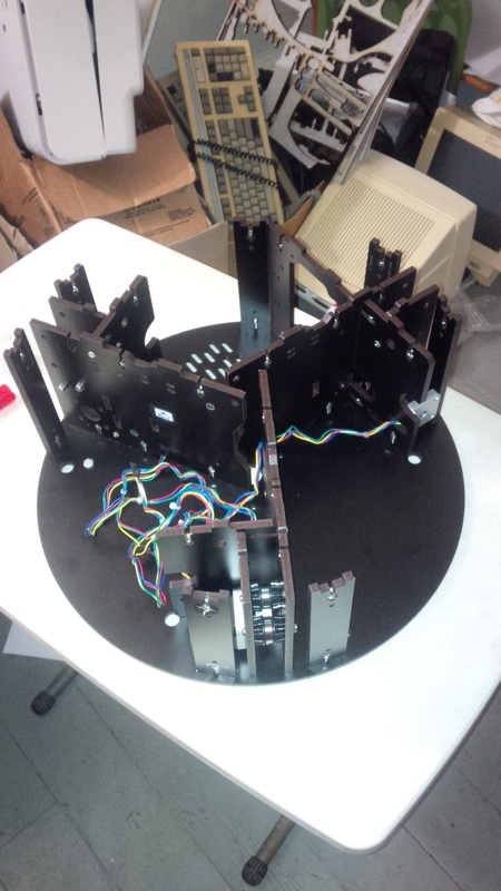
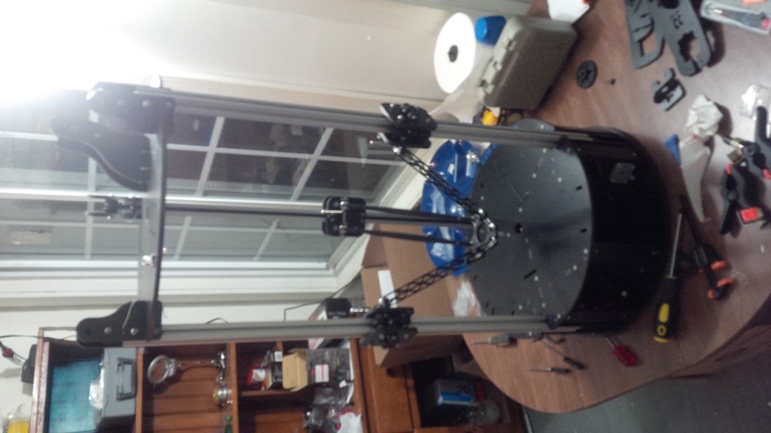
It's starting to look like something...YEAH!!
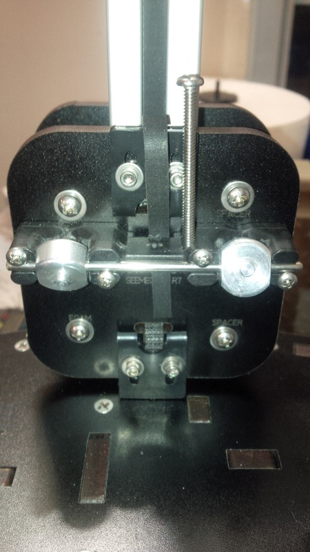
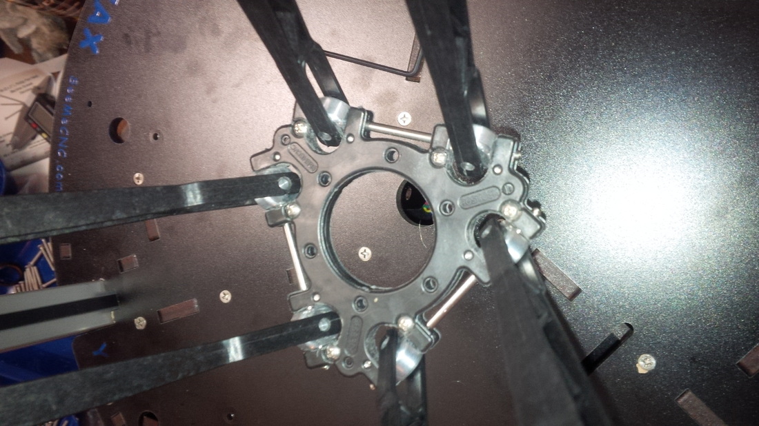
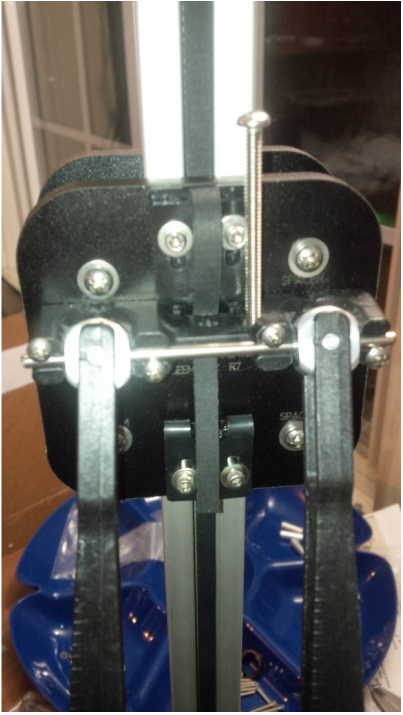
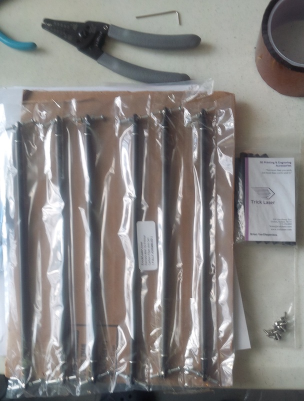
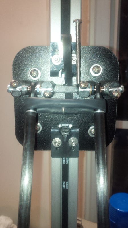
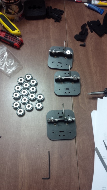
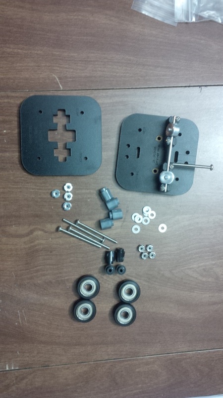
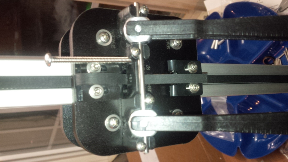
Now that we have the towers and the top in place it is time to get started on the "Cheapskates". First though I went ahead and installed the end stops and ran the wiring for them through the middle of the extrusions that make up the three towers. "Cheapskates" is the name SeeMeCNC has given to their method of moving up and down the towers while holding the arms and end effector in place. It consists of two melamine plates, 5 bearings (like the ones used for skateboards), regular spacers, and eccentric spacers to adjust how the bearings press onto the towers. There are three "Cheapskates" because there are only three towers. You complete half of the "Cheapskate" construction off of the Rostock Max and the other half on the actual towers. This is also where you will be installing the u-joints that hold the arms and the end effector. Since these parts are injection molded you are not able to get them within the tolerances needed for the u-joints to move freely with no "slop" or side to side motion. This is where you have to pull out your file and start shaping those u-joints so they will pass the "flick test" (so they will freely spin in the joint a few times with no side to side motion when you flick them with your finger). You will notice that in the pictures for a little while I have the original u-joints and then no more, this is because I decided to order separate arms from "Trick Laser" that do not use the u-joints. The reason I did this was because in my opinion I believe leaving the sanding and filing for a perfect fit up to the builder leaves too much room for error. Not that I don't think it can be done, because it can and has, just because on such a precise part I didn't want to risk my prints quality.

Once you have them on the towers you need to adjust the eccentric bearings so that all four bearings are touching the t-slot and so they freely roll when it is moved. You have it adjusted correctly when you can toss the "cheapskate" up the tower and have it come back down to your hand with no sticking and no side to side motion. Now that you have them all adjusted correctly you can go ahead and install the 5th support bearing on the back side of the "Cheapskate". Next we get to install the timing belts! YEAH!!
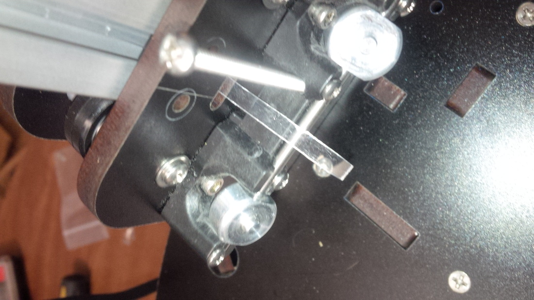
I thought getting the belts installed was going to be a horrific event, turns out it was rather simple using a method by one of the SeeMeCNC Forum members using a little piece of plastic cut in a long strip. On the "Cheapskates" there are two little slots on top and bottom of the plate that faces in on the machine. You need to route the timing belt through the bottom slot and secure it with the supplied belt clip, down through the base, around the gear and idler bearings, run it inside the t-slot channel, around the top tension bearing, and finally through the tiny little slot in the top and secure it with a supplied clip. Phew!

As you can see getting the belt through those slots may impose a little trouble, but not with the plastic strip method. You just slide the strip through the slot and up the t-slot channel then slide the belt down along the plastic and then grab both ends of the plastic with the belt and just push the belt through, the belt follows the path of the plastic strip flawlessly!
Now would be a good time to file or sand the u-joints on the end effector, which I did even though I had some Carbon Fiber arms coming from Trick Laser. The same principle applies to the end effector as did for the u-joints on the "Cheapskates". Once done attach your arms to the "Cheapskates" and the end effector.
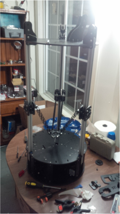
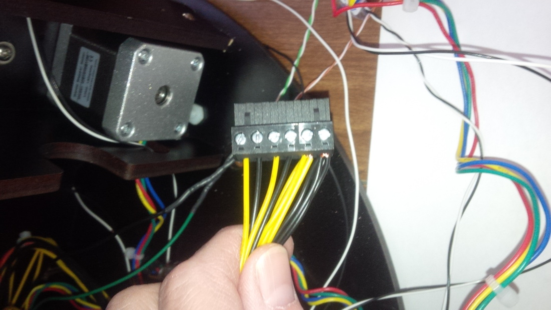
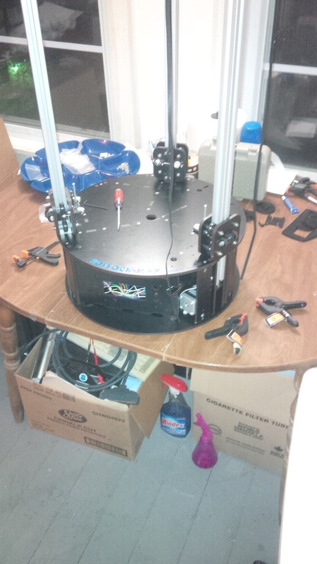
Now she is really starting to look like a Rostock! Next I installed the power supply and cut and grouped my wires I would need to connect to the RAMBo board and for the power switch. I used 6 yellow and six back to connect to the RAMBo, 4 of each for the heated bed and then one set for each of the other 2 spots on the power plug. Then I had to extend the green wire and a black wire for the power switch.
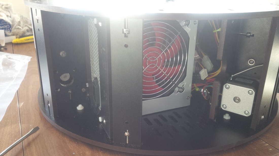
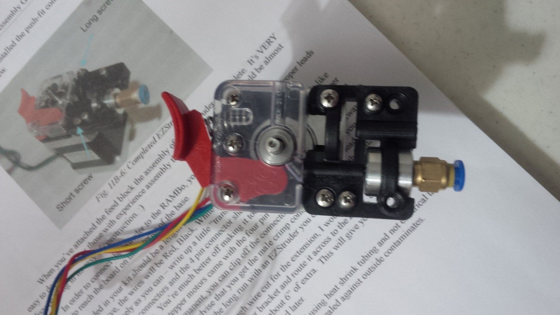
Next up I assembled the "EZ-Struder" which is the extruder that is connected to the hot end with a bowden tube setup. Once the extruder was assembled I secured it to the bottom of the top plate along with the spool holder on top of the machine. I had to extend the wires for the extruder to reach the electronics bay, I used JST connectors in case I need to remove the extruder at some point, just makes it a bit easier and cleaner I think. Installing the RAMBo board was kind of a pain since I had to get the screw in through the hole then a spacer into the wall inside the electronics bay.

This is about when my Trick Laser Carbon Fiber arms came in the mail so I promptly opened that package and proceeded to install the awesome Trick Laser arms in place of the stock SeeMeCNC arms that came with my kit. I cant really give my opinion about weather or not these arms provide better prints as I never actually printed with the stock arms but there are plenty of posts on the SeeMeCNC Forum that attest to the fact that they are without a doubt much better. Makes sense though seeing how the movement was much smoother with the Trick Laser arms when I would manually move the end effector around. Just a side note that once you have everything hooked up and plugged in you don't want to make the belts move too much under manual power as it does build up a bit of a charge that may or may not go back into your board and fry it.

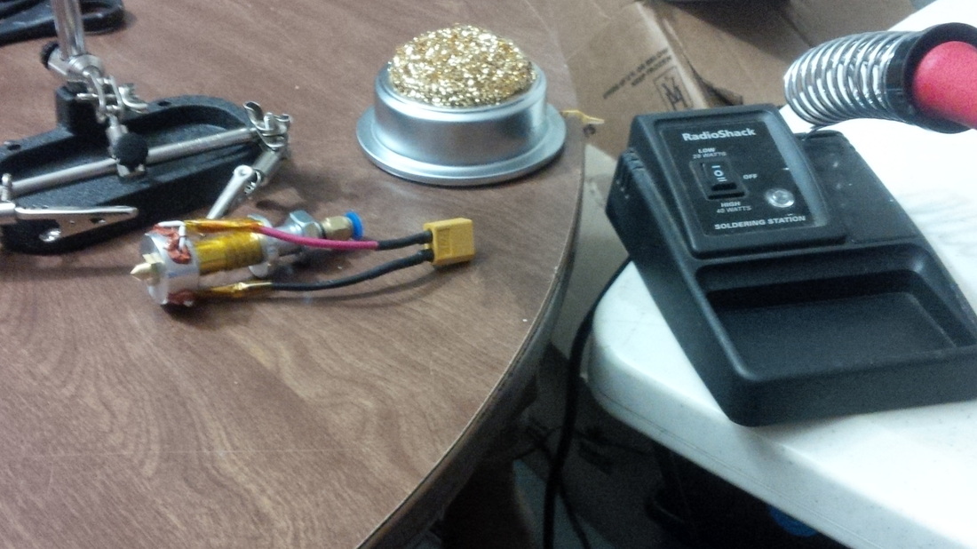
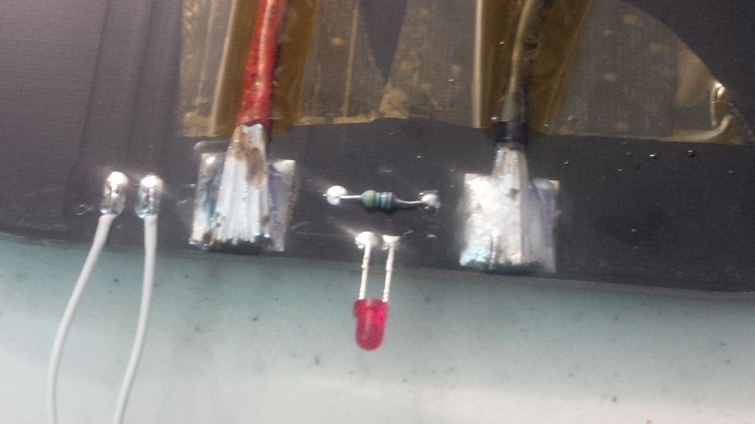
Another note now that I think about it, in the beginning when you put together the hot end you should probably install the thermistor into the middle of the "Onyx" heated bed so that the RTV has time to cure on that as well. I had to wait a whole day before moving forward with the build when I got to this point!
Once the RTV has cured fully you can solder the thermistor leads to the pads right next to the middle of the bed and then solder your wiring for the power and thermistor as well as the LED and the little resistor. I used 13 gauge wires for the power wires and the included wire for the thermistor. This part isn't hard it just takes a while to get the solder to flow on the power pads as they are so large and the bed seams to absorb the heat!

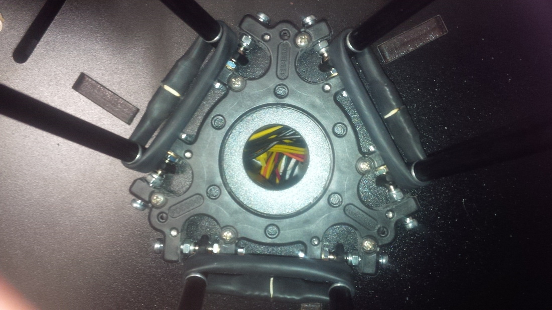
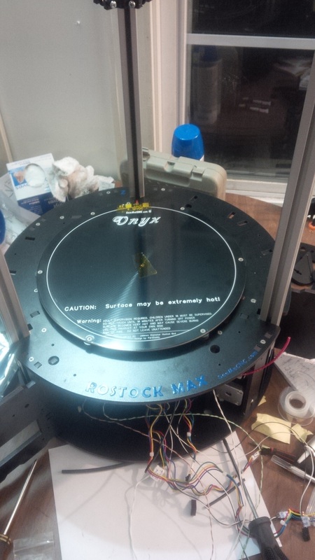
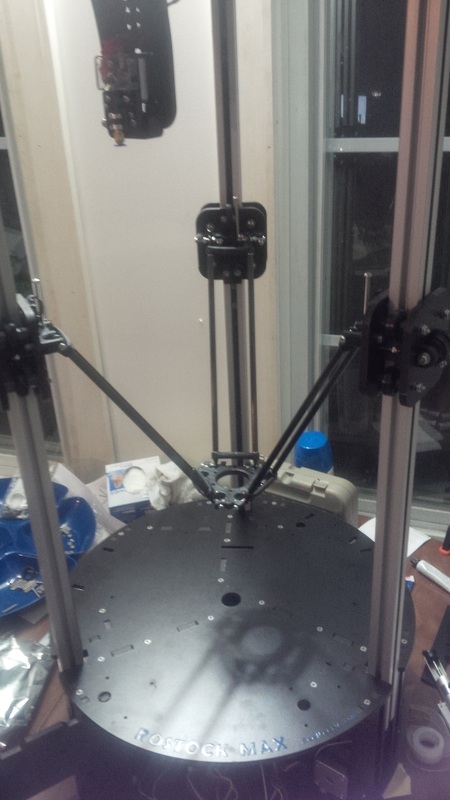
Now we can go ahead and attach the "Onyx" heated bed to the top of the base. You have to get this little snowflake shaped spacer lined up with the holes on top of the base with spacers in between the base and the snowflake then the "Onyx" goes on top of that and the screws through everything secured by little t nuts that were put in place when assembling the base. To make this task easier I super glued the little spacers to the bottom of the snowflake so I could hold the bed against the snowflake and put the screws through as I got the holes lined up. This part was a little bit of a pain as well! For the "Onyx's" power wires I used an XT-60 connector to a little pig tail in case I ever needed to take the heated bed out as this would make it a bit easier to just unplug it.
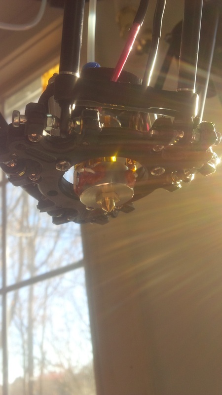
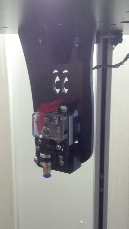
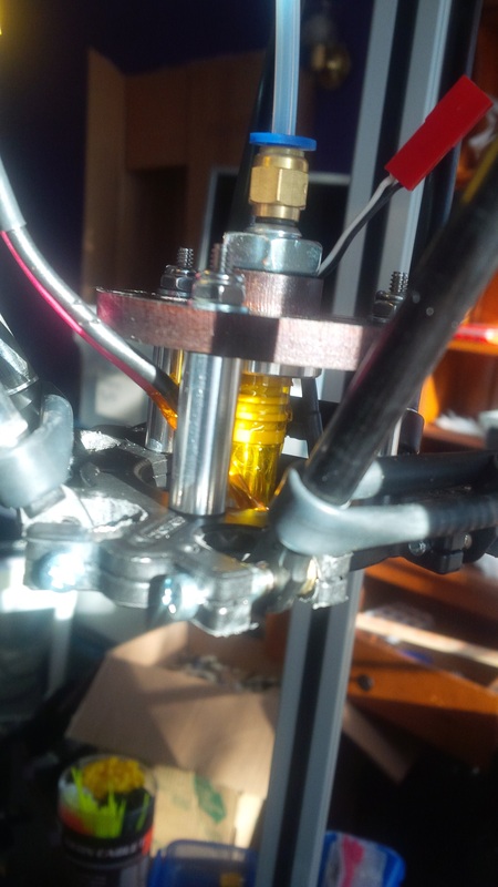
Now I installed the hot end we had completed earlier in the build with the included plate and spacers. Then I placed the bowden tube into the push to fit connectors on the extruder and the hot end. All of our wiring for the hot end will follow the same path as this tube then up through the middle hole in the top with the extruder wires. You want to go ahead and secure the wiring to the tube with some zip ties and then continue with the zip ties for the rest of the wiring to keep it all nice and neat.


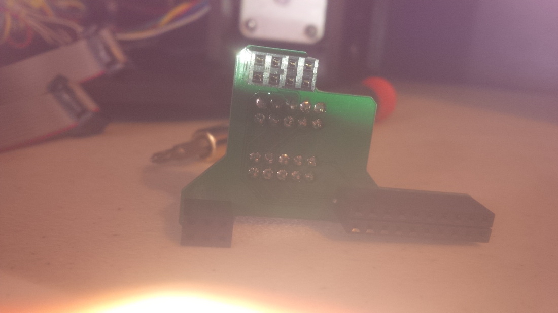
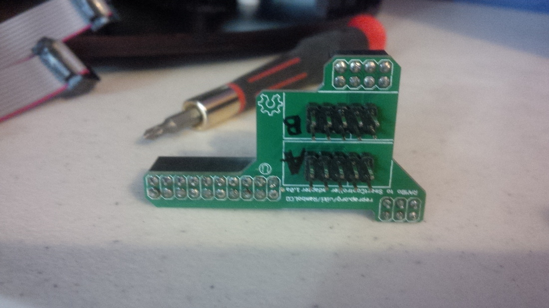
Getting close to the end, I was so excited, I swear I didnt sleep much the last two days of the build I was just so crazy about wanting to see this thing working! So, the next thing I did was to solder together the adapter for the "RepRapDiscount LCD" to hook up to the RAMBo board. Once I had that done I started hooking up the rats nest of wires I had collecting in the electronics bay!

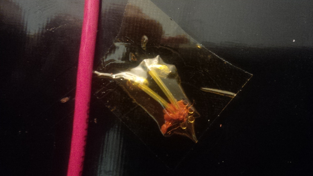
Sorry for the crappy picture! :-(
Now lets get those wires hooked up and get this thing going!

YEAH!!! Finally, finally, finally, I had everything hooked up and ready to go. I plugged in my power supply and then the moment of truth, I flipped the switch. NOTHING! What?! Seems when I was soldering the green and black wires to the switch I left the iron on the leads a little too long and they started to melt so the switch was no longer making a connection. At that moment I wanted to see this thing power up so bad I just cut the bad switch out of the picture and hot wired my Rostock Max so I could finally bring it to life! There we go, no it was working! Everything was good, the LCD display came on as it should and everything! I cant explain how happy I was at this moment! Finally after all that work, arguing with my wife about how much time im spending working on it, and sleepless nights it is working! Its a good feeling to put this much of yourself into something for incredible results! I wont waste any more time, I'm gonna show you what it looks like in its new home right now.
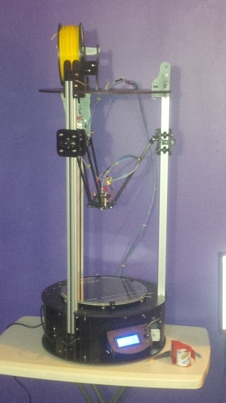
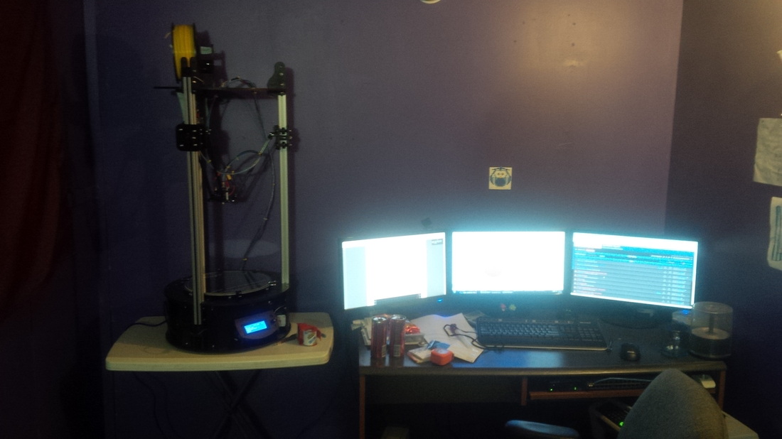
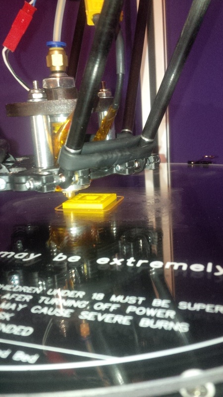
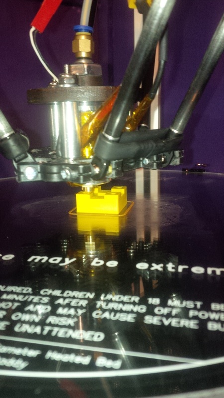
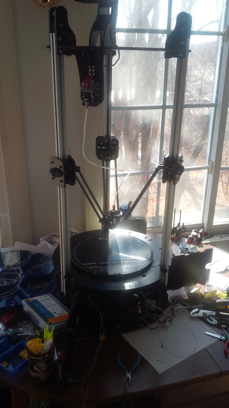
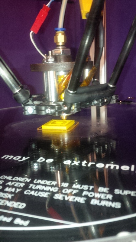
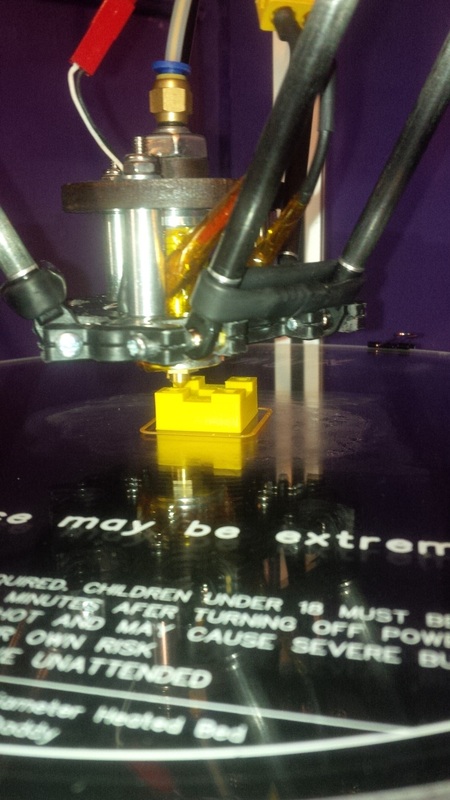
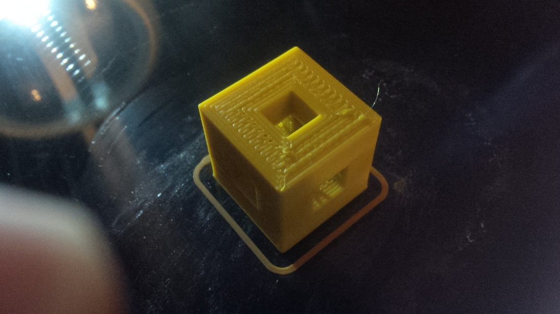
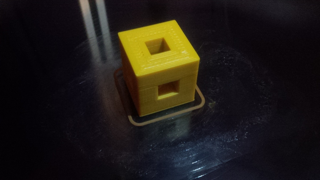
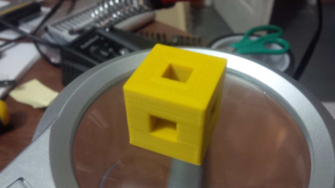
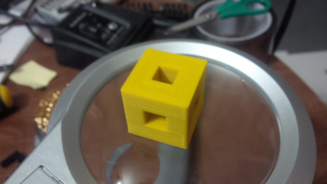
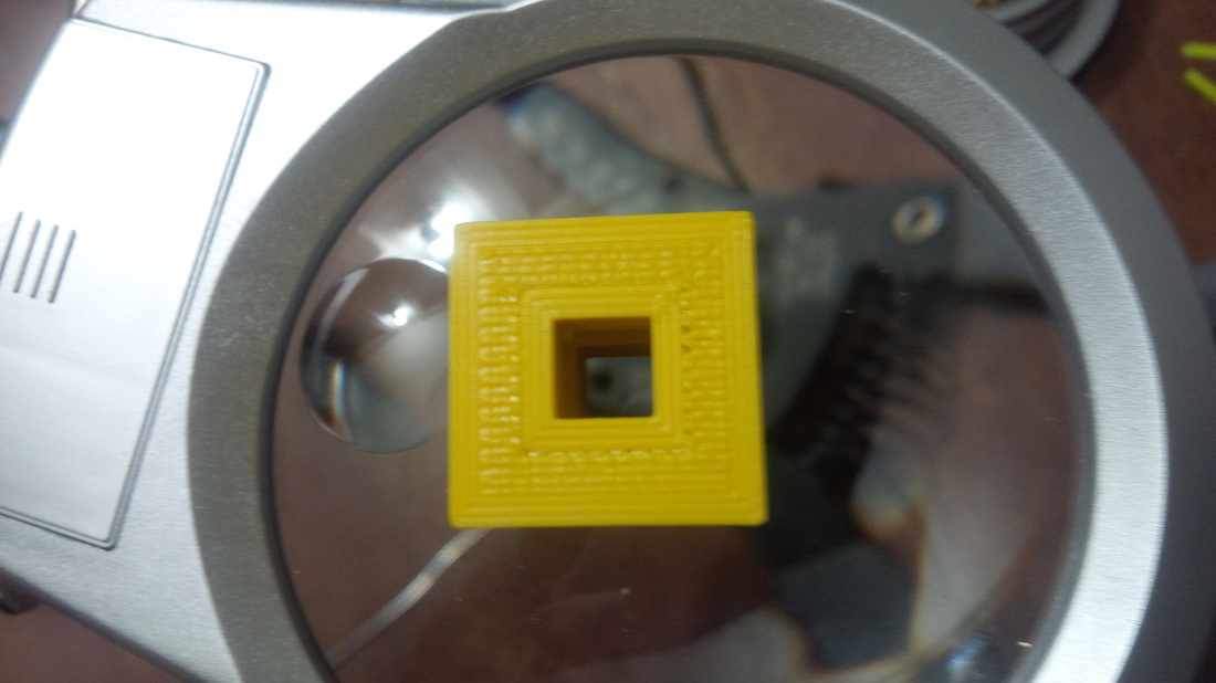
She is sexy isn't she?! Its a great looking machine! I think it goes well in my office / workshop area. I wasn't quite done yet though, I still had to calibrate this beast! Calibration was a little tedious but all in all not too bad, took me about another hour or so and I was ready for my first print. What did I print first? Well of course it had to be a calibration cube just like in the build manual. My calibration cube came out really well, I have got to give props to GeneB over on the SeeMeCNC Forum for all his hard work on the Build Manual, without which I don't know if I could have finished this build so easily and quickly! Well that's it for now, I will keep you guys posted on things as they progress with me and my Rostock Max over on the i3DTECH BlogSpot, I'm gonna keep this page specifically for my build log. I'll leave you guys with the pictures of my first ever printed calibration cube. As always...HAPPY PRINTING GUYS!!!!


 RSS Feed